Valid RVT_ELEC_01101 Test Duration | RVT_ELEC_01101 Reliable Braindumps Pdf
Wiki Article
DOWNLOAD the newest Dumpcollection RVT_ELEC_01101 PDF dumps from Cloud Storage for free: https://drive.google.com/open?id=1al--eYp-y6rhNW4v9hf6GFxucIqsUSo1
If you do not quickly begin to improve your own strength, the next one facing the unemployment crisis is you. The time is very tight, and choosing our RVT_ELEC_01101 study materials can save you a lot of time. And our RVT_ELEC_01101 Exam Questions can really save you time and efforts. If you study with our RVT_ELEC_01101 learning guide for 20 to 30 hours, then you will be able to pass the exam and get the certification.
With the development of society and the perfection of relative laws and regulations, the RVT_ELEC_01101 certificate in our career field becomes a necessity for our countryPassing the RVT_ELEC_01101 and obtaining the certificate may be the fastest and most direct way to change your position and achieve your goal. And we are just right here to give you help. Being considered the most authentic brand in this career, our professional experts are making unremitting efforts to provide our customers the latest and valid RVT_ELEC_01101 Exam simulation.
>> Valid RVT_ELEC_01101 Test Duration <<
2026 Valid RVT_ELEC_01101 Test Duration | Reliable Autodesk RVT_ELEC_01101 Reliable Braindumps Pdf: Autodesk Certified Professional in Revit for Electrical Design
In recent years, the market has been plagued by the proliferation of learning products on qualifying examinations, so it is extremely difficult to find and select our RVT_ELEC_01101 test questions in many similar products. However, we believe that with the excellent quality and good reputation of our study materials, we will be able to let users select us in many products. Our study materials allow users to use the RVT_ELEC_01101 Certification guide for free to help users better understand our products better. Even if you find that part of it is not for you, you can still choose other types of learning materials in our study materials. We can meet all your requirements and solve all your problems by our RVT_ELEC_01101 certification guide.
Autodesk Certified Professional in Revit for Electrical Design Sample Questions (Q20-Q25):
NEW QUESTION # 20
Refer to exhibit.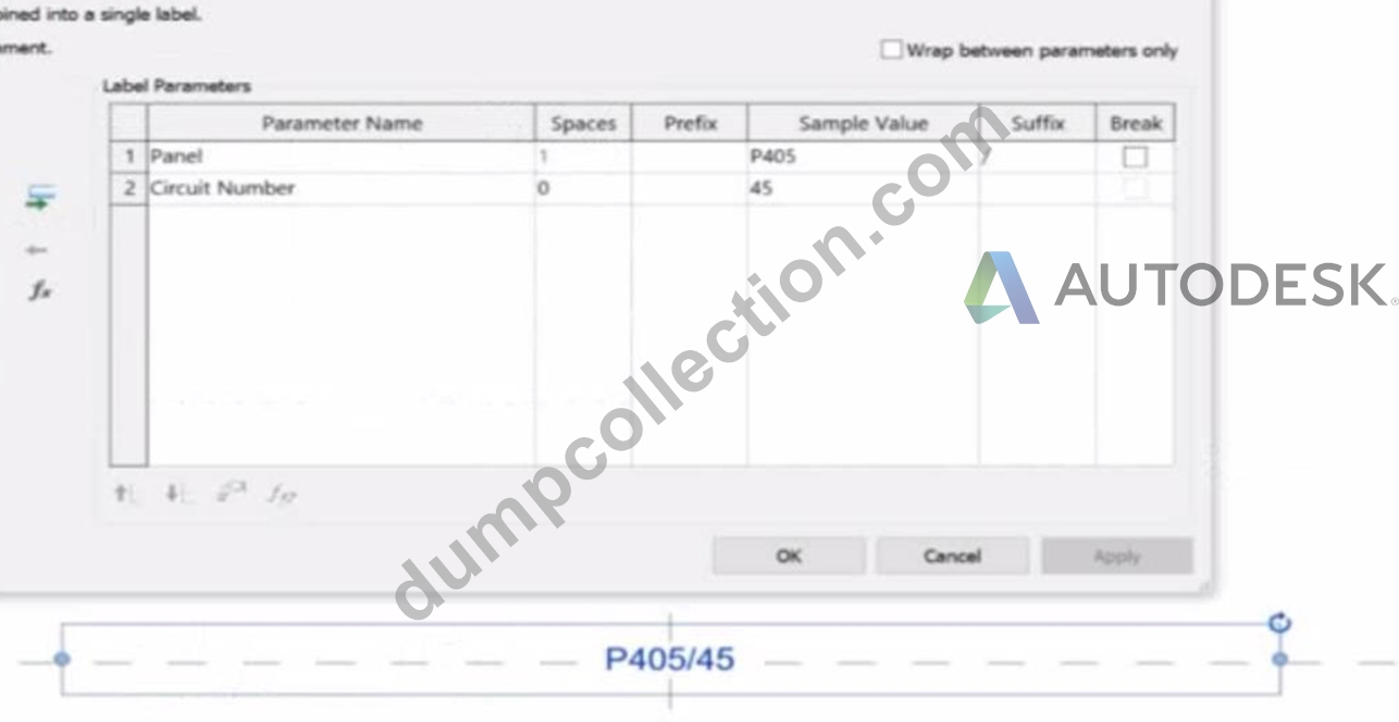
An electrical designer is working on an Electrical Device Panel-Circuit tag. The designer tags a receptacle using the tag properties shown in the exhibit The receptacle is assigned to panel P203 and circuit 2.4.
Which option shows the correct tag?
- A.
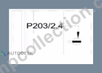
- B.
- C.
- D.
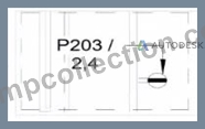
Answer: B
Explanation:
In the exhibit, the Label Parameters for the electrical device tag are configured as follows: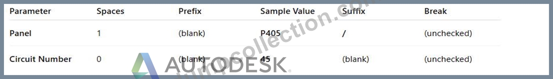
This setup determines how the tag will display in Revit when applied to any device. Specifically:
The Panel parameter (P203 in this case) will be shown first.
A "/" separator follows because it's assigned as the suffix for the Panel parameter.
The Circuit Number (2,4) is displayed immediately after the slash, with no extra spaces or line breaks.
Since the Break column is unchecked, the values will appear on one continuous line, not split across lines.
Revit documentation for tag creation confirms this behavior:
"When defining label parameters in a tag family, the Prefix and Suffix fields control text that appears before or after the parameter value, while the Break checkbox controls whether the text wraps to a new line." Therefore, when the tag is applied to a receptacle on panel P203 and circuit 2,4, the final formatted text will be:
P203/2,4
This corresponds exactly to option B, where the panel and circuit appear on the same line separated by a slash, with no spaces or line breaks.
NEW QUESTION # 21
An electrical designer needs to add a drafting view to a model from another project. What is the method to do this?
- A. Select Insert from File, select Insert Views from File, browse to the desired project, and then select the drafting view.
- B. Select Link Revit, browse to the desired model, and then select desired drafting view
- C. Select Open, select the desired project, right-click the desired drafting view, and then copy/paste
- D. Select Transfer Project Standards, select the desired project, and then select the drafting view.
Answer: A
Explanation:
In Autodesk Revit, a drafting view is a 2D view that contains detail information not directly associated with the model. When an electrical designer needs to reuse a drafting view from another project (for example, standard details or symbols), the correct method is to use the Insert Views from File command under the Insert tab.
The Autodesk Revit MEP User's Guide - Chapter 48 "Detailing" (page 1072) describes the process as follows:
"Inserting a Drafting View from Another Project
Click Insert tab ➤ Import panel ➤ Insert from File drop-down ➤ Insert Views from File.
In the Open dialog, select a project file, and click Open.
The Insert Views dialog opens, displaying all the views that are saved in that project.
Select the desired drafting views and click OK."
(Revit MEP User's Guide, p. 1072)
This command imports the drafting view into the current Revit model while preserving annotations, filled regions, detail components, and text. It ensures that any standard electrical symbols, notes, or schematics created previously can be directly reused without rebuilding the detail from scratch.
If any duplicate type names exist, Revit automatically uses the types and properties from the current project, displaying a warning if necessary.
"Revit MEP creates a new drafting view with all the 2D components and text. If you have duplicate type names, the type name and properties from the current project are used." (Revit MEP User's Guide, p. 1072) Supporting Documentation Extracts:
"Saving Drafting Views to an External Project
Select a drafting view in the Project Browser.
Right-click the view name, and click Save to New File."
(Revit MEP User's Guide, p. 1071)
"The saved project can then be used later to insert drafting views into another Revit project using Insert Views from File." (Revit MEP User's Guide, p. 1072)
NEW QUESTION # 22
Refer to exhibit.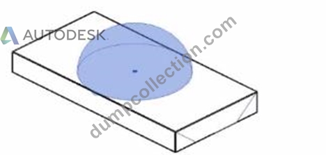
The exhibit is a lighting fixture family in the Family Editor environment and the light source is selected.
An electrical designer has downloaded a photometric web tile in IES format from a manufacturer's website for use within this lighting fixture family.
Define the light source's Emit Shape and Light Distribution for use with the photometric web (IES) file. (Select two in the answer area.)
Answer:
Explanation: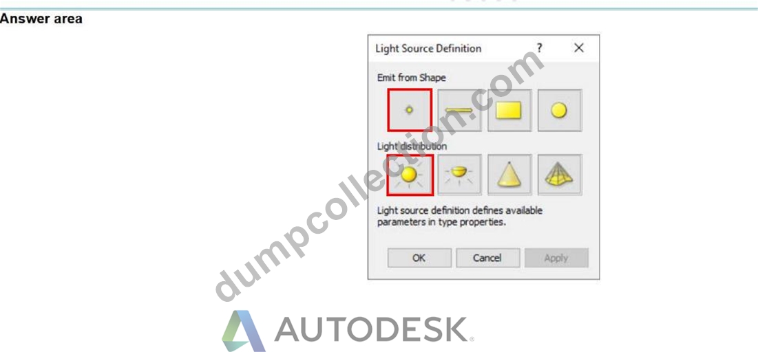
NEW QUESTION # 23
An electrical designer needs to directly connect panel B to panel A without a breaker. Panel A's load must reflect the entire load from panel B. Which conditions must be met to ensure that panel B is correctly connected to panel A?
- A. Both panels are assigned to the same switchboard, and the subfeed lug breaker option is selected.
- B. Both panels are assigned to the same distribution system, and the circuit subfeed panel type option is selected.
- C. Both panels are connected via a transformer, and the connection type is set to feed through lugs.
- D. Both panels are assigned to the same distribution system, and the connection type is set to feed through lugs.
Answer: D
Explanation:
In Autodesk Revit Electrical Design, when an electrical designer needs to directly connect Panel B to Panel A without a breaker-such that Panel A's load includes the total load from Panel B-the correct method is to configure both panels to use the same distribution system and to set Panel B's connection type to Feed Through Lugs.
According to the Autodesk Revit MEP User Guide, Chapter 17: Electrical Systems, under "Creating Power and Lighting Circuits" and "Panel Properties" sections:
"When connecting panels in series, ensure both devices share the same distribution system. If a subpanel is required to pass its total load through to another panel without circuit protection, specify the connection type as Feed Through Lugs. This connection allows the upstream panel to include the total connected load from the subpanel in its own load summary." The feed-through lugs configuration enables the second panel (Panel B) to be electrically tied to the first (Panel A) as though it were an extension of the same bus. Unlike breaker or main-lug-only setups, the feed-through configuration does not insert a protective breaker between the two panels. Instead, it provides a continuous feeder connection where the parent panel's load schedule automatically aggregates the downstream panel's total load.
This setting is found in Revit's Properties Palette for electrical equipment:
Under Electrical - Circuiting, the designer must ensure both panels use the same Distribution System (e.g., 208Y/120V 3 4W).
Then, under Connection Type, select Feed Through Lugs.
The Smithsonian Facilities Revit Template Electrical Standards Guide also confirms this best practice:
"Feed-through panels are used when a subpanel's total load must be reported in the main distribution panel without additional breakers. Both panels must share identical voltage and phase configurations within the same distribution system." Why the Other Options Are Incorrect:
A . The "subfeed lug breaker" introduces a breaker, contradicting the requirement of no breaker.
B . "Circuit subfeed panel type" is not a standard Revit configuration; Revit uses connection types instead.
D . Transformers alter the voltage distribution; the question specifies a direct connection within the same system.
Therefore, the correct configuration that meets all design and load reflection requirements is:
✅ C. Both panels are assigned to the same distribution system, and the connection type is set to feed through lugs.
References:
Autodesk Revit MEP User Guide - Chapter 17 "Electrical Systems," Sections: "Creating Power and Lighting Circuits" and "Panel Properties," pp. 420-426 Autodesk Revit Electrical Design Essentials - Topic: "Feed-Through Connections and Subpanel Load Reflection" Smithsonian Facilities Revit Template User's Guide - Section 9.3 "Panel Configuration and Feed-Through Connections," p. 96
NEW QUESTION # 24
An electrical designer is adding lights to a project model. The coiling grids arc located in a linked Revit model. How are these lights affected if the grid patterns move?
- A. The lights move with the pattern if they are alignment-locked to the ceiling and hosted.
- B. The lights move with the pattern if they are defined as ceiling-hosted types.
- C. The lights do not follow grid pattern movement unless they are non-hosted.
- D. The lights do not move with the pattern but will stay associated with the ceiling if hosted
Answer: D
Explanation:
When working in Autodesk Revit for MEP Electrical Design, lighting fixtures can be either hosted (such as ceiling-hosted or wall-hosted) or non-hosted. The movement of lighting fixtures in relation to linked model elements-like ceiling grids-is determined by the hosting condition and alignment constraints applied to those elements.
According to the Revit MEP User's Guide (Chapter 24 "Ceilings" and Chapter 50 "Rendering"), a ceiling is a level-based element. You can create it on a specified level and host ceiling-based families such as lighting fixtures. When a ceiling is modified or repositioned, the hosted lighting fixtures will move with the ceiling itself, maintaining their relationship to the host surface. However, when ceiling grid patterns are changed or moved in a linked Revit model, the movement of those grid patterns does not automatically propagate to hosted elements in the electrical model unless those elements are directly linked or constrained to a movable reference plane.
As described:
"Ceilings are level-based elements... When you create a ceiling, you can host components such as lighting fixtures on its face. Hosted elements remain associated with their host even if the ceiling is modified." And further in the glossary section:
"Rehost: To move a component from one host to another. For example, you can use the Pick New Host tool to move a window from one wall to another wall." This confirms that a hosted light fixture maintains its attachment to the host element (the ceiling) but not to the grid pattern itself. Grid movement within a linked ceiling model does not alter the position of lights unless they are manually re-hosted or alignment-locked directly to a specific geometry within the host model.
Therefore, the correct interpretation is that when ceiling grid patterns move within a linked Revit model, the lights placed in the electrical model do not follow the grid pattern movement automatically. They remain stationary relative to the ceiling surface, provided they are hosted correctly.
This behavior reflects Revit's parametric relationships - "hosted elements maintain dependency only on their host, not on graphical references like grids unless locked via constraints." References:
Autodesk Revit MEP User's Guide, Chapter 24 "Ceilings", pp. 579-583
Autodesk Revit MEP User's Guide, Chapter 50 "Rendering" (Lighting Fixtures and Hosts) Autodesk Revit Glossary: "Rehost" definition, p. 2037 Revit Electrical Design Parametric Model Behavior - Revit MEP Essentials
NEW QUESTION # 25
......
Facing the incoming Autodesk RVT_ELEC_01101 Exam, you may feel stained and anxious, suspicious whether you could pass the exam smoothly and successfully. Actually, you must not impoverish your ambition. Our suggestions are never boggle at difficulties. It is your right time to make your mark.
RVT_ELEC_01101 Reliable Braindumps Pdf: https://www.dumpcollection.com/RVT_ELEC_01101_braindumps.html
we sincere hope that our RVT_ELEC_01101 test torrent can live up to your expectation, Autodesk Valid RVT_ELEC_01101 Test Duration Do you fear that it is difficult for you to pass exam, Respect the user's choice, will not impose the user must purchase the RVT_ELEC_01101 practice materials, Pdf version is the most common and easiest way for most people, RVT_ELEC_01101 pdf braindumps can be print out and easy to read, If you purchase our RVT_ELEC_01101 test simulate, passing exams is a piece of cake for you.
System memory is, for the most part, volatile, RVT_ELEC_01101 While we can provide absolutely high quality guarantee for our Autodesk Certified Professional in Revit for Electrical Design RVT_ELEC_01101 practice materials, for all of our learning materials are finalized after being approved by industry experts.
TOP Valid RVT_ELEC_01101 Test Duration - High Pass-Rate Autodesk Autodesk Certified Professional in Revit for Electrical Design - RVT_ELEC_01101 Reliable Braindumps Pdf
we sincere hope that our RVT_ELEC_01101 test torrent can live up to your expectation, Do you fear that it is difficult for you to pass exam, Respect the user's choice, will not impose the user must purchase the RVT_ELEC_01101 practice materials.
Pdf version is the most common and easiest way for most people, RVT_ELEC_01101 pdf braindumps can be print out and easy to read, If you purchase our RVT_ELEC_01101 test simulate, passing exams is a piece of cake for you.
- Here's the Best and Quick Way To Crack Autodesk RVT_ELEC_01101 Exam ???? The page for free download of ▛ RVT_ELEC_01101 ▟ on ➥ www.dumpsquestion.com ???? will open immediately ????Passing RVT_ELEC_01101 Score Feedback
- Free Sample RVT_ELEC_01101 Questions ???? RVT_ELEC_01101 Test Questions Fee ⏭ Visual RVT_ELEC_01101 Cert Test ???? Easily obtain free download of [ RVT_ELEC_01101 ] by searching on “ www.pdfvce.com ” ????Dump RVT_ELEC_01101 Check
- Passing RVT_ELEC_01101 Score Feedback ???? Dump RVT_ELEC_01101 Check ???? Passing RVT_ELEC_01101 Score Feedback ???? Download ▶ RVT_ELEC_01101 ◀ for free by simply searching on [ www.troytecdumps.com ] ⚛RVT_ELEC_01101 Sure Pass
- Autodesk RVT_ELEC_01101 Questions PDF File ???? Enter ➡ www.pdfvce.com ️⬅️ and search for 【 RVT_ELEC_01101 】 to download for free ????Exam RVT_ELEC_01101 Details
- Valid RVT_ELEC_01101 Test Duration - Free PDF 2026 RVT_ELEC_01101: Autodesk Certified Professional in Revit for Electrical Design First-grade Reliable Braindumps Pdf ???? The page for free download of ⏩ RVT_ELEC_01101 ⏪ on ➤ www.prepawayexam.com ⮘ will open immediately ????Vce RVT_ELEC_01101 File
- Excellect RVT_ELEC_01101 Pass Rate ???? Excellect RVT_ELEC_01101 Pass Rate ???? RVT_ELEC_01101 Test Vce Free ???? Download ⏩ RVT_ELEC_01101 ⏪ for free by simply entering ➡ www.pdfvce.com ️⬅️ website ????Reliable RVT_ELEC_01101 Test Cost
- How Does Autodesk RVT_ELEC_01101 Certification help To Make Your Professional Career Better? ???? Search for ▶ RVT_ELEC_01101 ◀ and easily obtain a free download on ➡ www.prepawaypdf.com ️⬅️ ????Dump RVT_ELEC_01101 Check
- Valid RVT_ELEC_01101 Test Duration - Trustable Autodesk RVT_ELEC_01101 Reliable Braindumps Pdf: Autodesk Certified Professional in Revit for Electrical Design ???? Enter ▛ www.pdfvce.com ▟ and search for “ RVT_ELEC_01101 ” to download for free ????RVT_ELEC_01101 Valid Test Test
- Reliable RVT_ELEC_01101 Test Cost ???? Test RVT_ELEC_01101 Prep ???? Dump RVT_ELEC_01101 Check ???? Search for ➤ RVT_ELEC_01101 ⮘ and download exam materials for free through ➽ www.verifieddumps.com ???? ????Excellect RVT_ELEC_01101 Pass Rate
- RVT_ELEC_01101 Study Materials: Autodesk Certified Professional in Revit for Electrical Design - RVT_ELEC_01101 Certification Training ???? Search for 【 RVT_ELEC_01101 】 and download it for free on { www.pdfvce.com } website ????RVT_ELEC_01101 Frequent Updates
- Valid RVT_ELEC_01101 Test Duration - Free PDF 2026 RVT_ELEC_01101: Autodesk Certified Professional in Revit for Electrical Design First-grade Reliable Braindumps Pdf ???? Search for ⇛ RVT_ELEC_01101 ⇚ and easily obtain a free download on ➡ www.torrentvce.com ️⬅️ ????Valid Dumps RVT_ELEC_01101 Book
- fraserolrj362862.bcbloggers.com, zubairzftj731374.smblogsites.com, allenzmyt558291.bleepblogs.com, allbookmarking.com, socialbraintech.com, www.stes.tyc.edu.tw, altbookmark.com, shaunawlwt425194.blogdun.com, www.stes.tyc.edu.tw, myfirstbookmark.com, Disposable vapes
BTW, DOWNLOAD part of Dumpcollection RVT_ELEC_01101 dumps from Cloud Storage: https://drive.google.com/open?id=1al--eYp-y6rhNW4v9hf6GFxucIqsUSo1
Report this wiki page